Due to the development of power electronics technology, the static frequency converter composed of power semiconductor devices is now very mature, and thus the variable voltage variable frequency (VVVF) speed regulation of AC motors has become more and more popular, and its superiority is also widely known.
But frequency conversion speed control is still mainly used in medium and small capacity and low voltage motors, and in the mining, metallurgy, chemical industry, petroleum, building materials and other industrial sectors and water plants, power plants, using a large number of medium- and high-pressure fans, pumps, compressors and mixers, etc.
The power of these machines are in the hundreds of kilowatts or more, and some as high as thousands of thousands of kilowatts or even tens of thousands of kilowatts, which consume a very substantial amount of electricity.
Previously, most of these machines use constant-speed AC drive, and to the baffle, valve or empty put back to the method of output regulation, the loss of a lot of power for nothing.
Therefore, the use of frequency conversion speed control in such machinery, according to the requirements of the output amount of electrical means to change the output power, energy saving has great significance.

High voltage frequency conversion speed control
power supply of several issues
1.Tandem connection
In the case where the device requires high voltage and the device has limited voltage resistance, the device can be used in series to meet the requirements.
However, the use of devices in series, due to the dynamic resistance of each device and the pole capacitance is different, and there are steady state and dynamic voltage equalization problems.
If you take with the device and R and RC voltage equalization measures, will make the circuit complex, increased losses; at the same time, the device series connection on the drive circuit requirements are greatly improved, to try to do the same time as the series device conduction and shutdown.
Otherwise, due to the devices on and off time is not the same, bear the voltage is not uniform, will lead to device damage or even the collapse of the whole device.
2.Harmonic wave
This is a common problem for all AC/DC frequency converter, but it is more prominent in high power frequency control. Harmonic pollution of the grid, will be affected by other equipment on the same grid, and even affect the normal operation of the power system, harmonic currents also make the motor heating, loss increase, power factor drop, have to “derate” use.
3.Efficiency
The higher the power of the unit, the more important the issue of efficiency becomes. In order to improve efficiency, we must try to minimize the power switching device and the loss in the frequency conversion power supply.
Based on the above considerations, with the full-control power electronic device IGBT composition, used for AC motor frequency conversion speed control of high-voltage frequency converter, the use of “power unit” series connection of the new structure.
That is, with a number of low-voltage pulse-width modulation (PWM) frequency converter as a power unit, will be multiplexed according to the format of high-voltage frequency converter can be a better solution to these problems. Better solve these problems.
IGBT high-voltage frequency converter
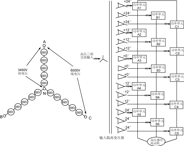
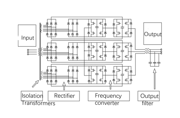
Figure 1(a),(b) shows the main circuit topology and connection diagram of a 6000V frequency converter. Each phase consists of five power units rated at 690V
Each phase consists of five power units rated at 690 V in series, so the phase voltage is 5 × 690 V = 3450 V, and the corresponding line voltage is 6000 V. (If four 480 V power units are connected in series with each phase, the output line voltage is 3300 V).
Each power unit is powered by each of the 15 secondary windings of the input isolation transformer, which are divided into 5 groups with a phase difference between each group. In Fig. 1(b), the middle △ connection is used as a reference (0°), and there are two sets of 4 windings at the top and bottom that are 12°,24° ahead (+) and behind (-), respectively. The desired phase difference angle can be realized by different coupling groups of the transformer.
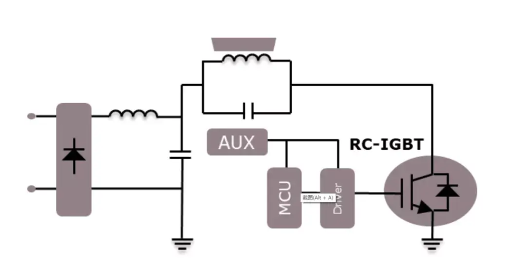
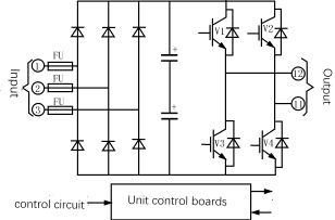
Each power unit in Fig. 1 is a three-phase input, single-phase output low-voltage PWM voltage frequency converter composed of insulated gate bipolar transistors (IGBTs), and the main circuit is shown in Fig. 2.
The output voltage of each power unit is 1,0,-1 for three state levels, and the superposition of five units in each phase produces eleven different level grades, namely ±5, ±4, ±3, ±2, ±1 and 0. Fig.
3 shows the sinusoidal output voltage waveform synthesized in one phase. The high-voltage frequency converter constructed with this multiplication method is also called unit series multi-level PWM voltage frequency converter.

The high-voltage frequency converter shown in Figure 1 does not have the problem of device voltage equalization because each phase consists of five 690V power units connected in series, rather than using conventional devices connected in series to achieve high-voltage output.
Each power unit carries the full output current, but only 1/5 of the output phase voltage and 1/15 of the output power.
The frequency converter uses a multiplicative PWM technique, Figure 1 The frequency converter is modulated by five pairs of triangular carriers (each pair containing positive and negative phase signals) sequentially shifted by 12° from each other to modulate the fundamental waveform voltage.
The A-phase fundamental modulation of the resulting five signals, respectively, control A1 ~ A55 power units, can be superimposed to get the phase voltage waveform shown in Figure 3 with 11 steps.
It is equivalent to 30 pulse frequency conversion, the theory of the 29th harmonic can be canceled, the total voltage and current distortion can be as low as 1.2% and 0.8%, respectively, known as “perfect harmonic-free” (Harmony) frequency converter.
Its input power factor can reach more than 0.95, without the need to set up input filters and power factor compensation devices.
This series of inverter same phase power unit output the same fundamental voltage, series connection of the carrier wave between the unit staggered in a certain phase, each power unit of the IGBT switching frequency of 600Hz, when each phase has five power units in series, the equivalent output phase voltage switching frequency of 6kHz.
Power unit using a low switching frequency can reduce the switching loss, and high equivalent output switching frequency and multi-level can greatly improve the output switching frequency. And multiple levels can greatly improve the output waveform.
In addition to reducing the output harmonics, the waveform improvement also reduces the noise, du/dt value and torque pulsation of the motor. Therefore, this kind of frequency converter used for speed regulation power supply has no special requirements for the motor, can be used for ordinary high-voltage motors, and do not need to derate, and there is no special limitation on the length of the output cable.
Voltage-type power unit due to sufficient filter capacitance, the frequency converter can withstand -30% supply voltage drop and 5 cycles of power loss.
Although this main circuit topology increases the number of devices, the efficiency of the frequency converter is as high as 96% or more due to the very low IGBT drive power (peak of about 5W, less than 1W on average) and the lack of the need for voltage equalization circuits, suction correction circuits and output filters.
By the power unit constitutes another program of high-voltage frequency converter is the use of high-voltage IGBT devices to reduce the series connection of power units.
For example, with 3.3kV IGBT devices, two power units in series by the PWM voltage source inverter, can output 4160V medium voltage; if you want to 6000V high-voltage output, as long as the three units in series.
The number of power units and devices to reduce the loss and failure rate is also reduced. Figure 4 shows the electrical connection diagram of the frequency converter connected in series by two power units.
As the number of output voltage levels reduced, in order to obtain excellent performance, this time the inverter needs to have an output filter.
Each power unit of the above frequency converter receives commands from a central controller consisting of a microprocessor, and the control and communication signals are transmitted by optical fibers, which can maintain 5KV insulation and ensure good anti-interference and reliability.
In addition, due to the modular structure, all power units are identical and can be interchanged, each power unit and the device only 3 AC inputs, 2 AC outputs and three-way communication plug, unit maintenance and replacement is very convenient; such as the use of power unit bypass technology, which allows inverter in the case of damage to the power unit to continue to derate the operation.


